Basic Pump Disassembly Part Two

Basic Pump Disassembly Part Two
July 20, 2020 Comments Off on Basic Pump Disassembly Part TwoBasic Pump Disassembly Part Two
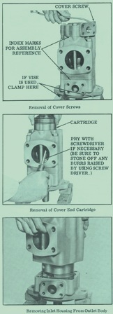
Next step to take is to take out the oring, backup ring and square sealing ring from the outlet support plate. Put a mark across the surface of the cartridge kit, the marking will help when you are putting the parts back together. Next take out the screws. Put in the inlet support plate and seal pack subassemblies off the cartridge. On this next step it is very important not to let the flex side plate to go in with the support plate. Center just enough of the flex side plate to be able to move it around. Put a clean piece of wood or some type of material over the ring and rotor to reverse the position of the cartridge.
Put in the outlet support plate and seal pack subassemblies off the flex side plate, but do not let the flex side plate to move over the ring and rotor. Again move the flex side plate enough that it doesn’t slide . Next left up the ring away from the rotor and vanes. Find where the arrow stamped into the rotor periphery. Take out the vanes and inserts so that you start at the arrow. Making sure to keep them in order when you look them over.
Take apart the flow control cover, take out the plug and spring from the cover. Take out the plug from the other end other end of the bore, while not letting the retaining ring to be removed unless it is damaged in some way. Put in the flow control and relief valve subassemblies from the cover.
Try not to slide flex plate over the ring and rotor, burrs on the ring or rotor can scratch the soft bronze surface.
Try not to take out the cartridge locating pins from the inlet support plate unless you see they are broken. The pins are a drive lock type and be hard to take out.
If you need further info on this topic, call us at 800-361-0068
sales@hydrostatic-transmission.com