Sundstrand Hydraulic Integrated Controller Part 2
Sundstrand Hydraulic Integrated Controller Part 2
February 22, 2016 Comments Off on Sundstrand Hydraulic Integrated Controller Part 2At our Hydrostatic Pump Repair Site, we offer many types of Hydrostatic Transmission Repair and information relating to Hydrostatic Parts
Today we will discuss:
Sundstrand Hydraulic Integrated Controller Part 2
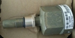
Installation:
Insert IHC into pump or motor housing, making sure that the O ring ,threaded washer and lock nut are installed on the IHC shaft and the threaded washer is loose and moves freely on the shaft.
Turn IHC clockwise until it contacts the speed ring on the pump or motor rotating element.
Turn counterclockwise half turn to establish a nominal gap of 0.227 in.
This step DOES NOT NEED TO BE MISSED. match mark the IHC and pump or motor housing to make sure the gap, above, is not changed as the lock nut is tightened.
Hold the IHC while tightening the lock nut (the relationship between match marks does not need to change).
Torque lock nut to 10 ft. lbs
The end cap doesn’t have to be aligned to show the IHC to sense shaft speed.
Installing Electrical Mating Connector
Put in the straight mating connector into IHC. Hand tighten knurled nut on mating connector.
The end cap can be rotated to use wiring harness attachment.
Rotating End Cap
Loosen two end cap screws so that the end cap freely rotates within the IHC housing.
Use a spanner wrench to insert into the holes in the end cap, rotate end cap to desired position.
Re-torque end cap set screws to 20 in lb.
Need further help with this topic, please leave us a comment and we will get back with you.
Call us at 800-361-0068
email: sales@hydrostatic-transmission.com