Part 2 of the M46 Series – Assembly of a Variable Displacement Hydraulic Pump
Part 2 of the M46 Series – Assembly of a Variable Displacement Hydraulic Pump
October 4, 2018 Comments Off on Part 2 of the M46 Series – Assembly of a Variable Displacement Hydraulic PumpAt our Hydrostatic Pump Repair Site, we offer many types of Hydrostatic Transmission Repair and information relating to Hydrostatic Parts
Today we will discuss:
Part 2 of Assembly of Variable Displacement Pumps Series 40 M46
Lock the adjustment by tightening the half nut to 18 to 27 lbs ft. while holding the plain nut from turning. Be sure to check the looseness between the spring,the screw or the piston and spring.
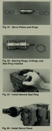
Put the piston bearing rings in the second set of grooves from the ends of the servo piston. Try not to deform the brass bearing rings. Put in the piston seal ex-pander O rings in the grooves closest to the ends of the servo piston. Put in a seal ring over the O ring in the groove opposite the piston centering screw. When installing the seal ring try not to stretch it any more than necessary.
Put lubricant on the bearing and seal rings and slide the piston assembly into the servo bore on the side of the housing opposite the main system ports. Slide the piston thru housing until the piston ring groove without a ring is just exposed. Then put lubricate on and put the second piston seal ring on and slide the servo piston back into the housing.
If your date code is 86-22 there is no need for a lead in chamber on the servo piston bore. You will need a piston ring compressor to compress the piston seal rings while putting in the servo piston on these pumps.
Put a new servo cover gasket on. Screw the cover onto the centering screw. Put in a new grade 8 flange head screws and torque to 11 to 13 lbs ft.
Now position the servo piston in the center of its travel by turning the centering screw. Grasp the centering screw from turning and put in a new lock nut. Tighten the lock nut to 13 to 16 lbs ft.
After the pump is assembled, there will be a final testing and adjustments will be made.
Put in the plain servo cover (without neutral adjustments0 with a new gasket. Put in a new grade 8 flange head screws and torque to 11to 13 lbs ft.
If we can assist you further about this topic, please leave us a comment or call us at 800-361-0068
and email at sales@hydrostatic-transmission.com