Vickers 45PGM Fixed Inline Hydraulic Piston Pump Repair
Vickers 45PGM Fixed Inline Hydraulic Piston Pump Repair
June 2, 2016 Comments Off on Vickers 45PGM Fixed Inline Hydraulic Piston Pump RepairAt our Hydrostatic Pump Repair Site, we offer many types of Hydrostatic
Transmission Repair and information relating to Hydrostatic Parts
Today we will discuss:
Vickers 45PGM Fixed Inline Piston Pump Repair
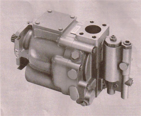
Put the whole unit with tubing into
an arbor press with drive spline up. See Figure 20.
Push the drive shaft through the bearing
and out of the unit. A 0. 001 inch press exists linking
the shaft and bearing so substantial force is necessary
to remove the bearing from the shaft.
Remove yoke as follows:
Remove yoke bearing parts (49 through
58). Be wary not to damage the seal on the long
pintle during removal If burrs are present on the pintle,
clean-up with an India stone before removing pintle
cover.
Keep shims (51) and (56) if possible and
use a micrometer to determine each shims thickness.
If the yoke pintle bearings are not faulty, the same
shims or new shims of the same thickness will be
needed to pre-load the bearings at the time of set up.
If shims (51) or (56) were damaged during disassembly, a yoke bearing pre-load modification will be vital at assembly.
Slide yoke (61) from side to side to release
yoke bearing races (59) or (60) within the housing. The
races are a normal slip fit but may be tight. Use an
open end wrench connecting the yoke and the pintle bearing
to help slide out the races. Use the amount of relevant pressure to
bearing (59) or (60) at the approximate center and al¬
low the bearing rollers to gently push the race out of
the housing.
Remove yoke (61) from housing (32).
Raise front shaft bearing (62) from the housing.
DO NOT remove the bearing race unless bearing was
found faulty. Refer to Figure 21 for bearing race
removal instructions.
Remove retaining ring (63) and push shaft
seal (64) out of the housing. Utilize a short piece of 1 ^”
heavy wall tubing as a tool or if the yoke was not re¬
moved, apply a tar ass rod and work from the inside of the
housing to drive shaft seal (64) from the housing.
REMINDER
Every one of the parts ought to be thoroughly cleaned and kept clean during examination and assembly. Clean every one of the detached parts, using a commercial cleaner that is similar in temperament with the system fluid. Compressed air may be used in cleaning, but it is the filtering that will remove the water and contaminates. Clean compressed air is predominantly useful in cleaning valve block passages.
INSPECTION REPAIR AND REPLACEMENT
MAKE NOTE OF
Restore all parts that do not meet the following requirement:
Examine vane pump shaft (17) for wear and chip¬-
ped splines.
Make sure bearing spacer (37) for burrs. Eliminate
small burrs with an India stone.
Scrutinize cylinder block face (38) for wear,
scratches and/or erosion involving the cylinders. Check
the spring, washers and retaining ring removed from
inside the cylinder block.
Ensure each cylinder block bore for unnecessary
wear. Use the piston and shoe sub-assemblies (39) for
this reason. The piston should be a close fit and
glide easily in and out of the bore. No bind can be tolerated.
If binding is obvious, clean the cylinder block
and piston, oil with clean hydraulic fluid and try
once more Even minor contamination of the fluid could
be the reason the piston will freeze up in the cylinder bore.
Examine both piston and shoe sub-assembly (39)
for a maximum end play of 0. 003 inch between the
piston and shoe.
Each shoe of the nine piston and shoe S/A’s
(39) must be ensured of thickness.It should be
within 0. 001 inch of each other. If out of tolerance,
restore the whole set of piston and shoe sub-assemblies simultaneously.
Check shoe plate (40) for too much wear and
cracking in the area of spherical washer (41). If serious
wear or cracks are found, change the shoe plate and
spherical washer at the same time.
Make sure spherical washer (41) for burrs, wear
and likely scratches due to pin (42) breakage. Re-
place if wear is unnecessary.
Look over pins (42) for equal length, too much
wear and probable bending. Replace all pins simultaneously
if one is not working.
The pin retainer (43) might develop burrs; move all burrs with an India stone.
Examine the bronze face of wafer plate (35) for
to much wear, scratches, and likely fracture. If
the wafer plate is cracked, make sure the new plate
rests flat next to the valve block at assembly and that
wafer plate pin (36) does not level too far and hold the
wafer plate away from the valve block.
Inspect shaft (48) for broken splines, burrs,
and wear in the area of shaft seal (64). Remove burrs
with an India stone. Wear in excess of 0. 005 T. I. R.
has to have shaft replacement to stop leakage.
45 gpm fixed inline piston pump
(M) pfb45-(F)rf-10/11
(M) pfb45 (F) LF 10/11
F6 PFB45(F) 10/11
I-3250 s
Call us 800-361-0068
email us at sales@hydrostatic-transmission.com
or we will be glad to answer any questions you may leave in the comments.