Meter in Circuitry
Meter in Circuitry
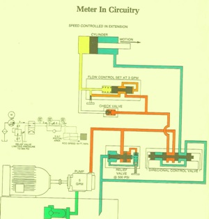
February 3, 2017 Comments Off on Meter in CircuitryMeter in Circuitry – speed controlled extentions
In the circuit illustrated, the restrictor type pressure compensated flow control valve is set for a 3 GPM. Relief valve setting is 500 PSI. Work load pressure is 200 PSI. The spring biasing the compensator spool has value of 100 PSI.
During system operation, the work load pressure of 200 PSI, plus the 100 PSI spring, bias the compensator spool.
The Pump attempts to push its total flow of 5 GPM through the needle valve orifice. When pressure ahead of the needle valve reaches 300 PSI, the compensator spool moves and cause a restriction for the incoming fluid. The pressure at the flow control inlet rises to the relief valve setting of 500 PSI. As the fluid passes over the restriction mode by the compensator spool, 200 PSI of the 500 PSI is transformed into heat. The pressure ahead of the needle valve is limited to 300 PSI. Of this 300 PSI, 200PSI is used to overcome the resistance of the load. 100 PSI is use to develop a flow rate through the needle valve orifice. The flow rate in this case is 3 GPM. The remaining 2 GPM is dumped over the relief valve
We welcome any questions on this subject or if you would like to comment on it, feel free to join in the conversation.
or call us at 800-361-0068
hydrostatic-transmission.com